
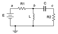
When analyzing resistor-inductor-capacitor circuits, remember that capacitor voltage cannot change instantaneously, thus, initially, capacitors behave as a short circuit. Once the capacitor has been charged and is in a steady-state condition, it behaves like an open. This is opposite of the inductor. As we have seen, initially an inductor behaves like an open, but once steady-state is reached, it behaves like a short. For example, in the circuit of Figure 9.4.1 , initially \(L\) is open and \(C\) is a short, leaving us with \(R_1\) and \(R_2\) in series with the source, \(E\). At steady-state, \(L\) shorts out both \(C\) and \(R_2\), leaving all of \(E\) to drop across \(R_1\). For improved accuracy, replace the inductor with an ideal inductance in series with the corresponding \(R_
Assuming the initial current through the inductor is zero and the capacitor is uncharged in the circuit of Figure 9.4.2 , determine the current through the 2 k\(\Omega\) resistor when power is applied and after the circuit has reached steady-state. Draw each of the equivalent circuits. 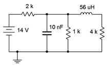 Figure 9.4.2 : Circuit for Example 9.4.1 . For the initial-state equivalent we open the inductor and short the capacitor. The new equivalent is shown in Figure 9.4.3 . The shorted capacitor removes everything to its right from the circuit. All that's left is the source and the 2 k\(\Omega\) resistor.
 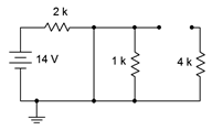 Figure 9.4.3 : Initial-state equivalent of the circuit of Figure 9.4.2 . We can find the current through the 2 k\(\Omega\) resistor using Ohm's law. \[I_ = \frac \nonumber \] \[I_ = \frac \nonumber \] \[I_ = 7 mA \nonumber \] Steady-state is redrawn in Figure 9.4.4 , using a short in place of the inductor, and an open for the capacitor. We are left with a resistance of 2 k\(\Omega\) in series with the parallel combination of 1 k\(\Omega\) and 4 k\(\Omega\), or 2.8 k\(\Omega\) in total.
 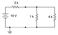 Figure 9.4.4 : Steady-state equivalent of the circuit of Figure 9.4.2 . \[I_ = \frac \nonumber \] \[I_ = \frac \nonumber \] \[I_ = 5mA \nonumber \]
This page titled 9.4: Initial and Steady-State Analysis of RLC Circuits is shared under a CC BY-NC-SA 4.0 license and was authored, remixed, and/or curated by James M. Fiore via source content that was edited to the style and standards of the LibreTexts platform.